G1 Topics
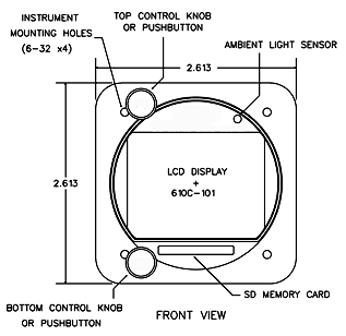
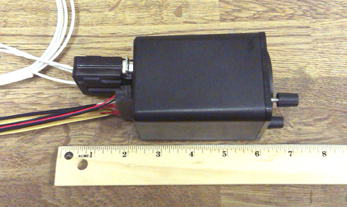
- Question 1, What is the size and dimensions of the G1?
- Question 2, What is Insight warranty?
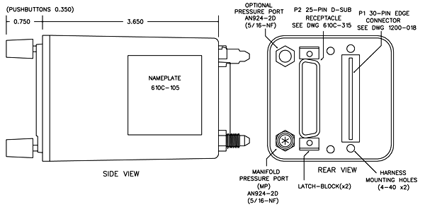
- Question 3, What is instrument depth?
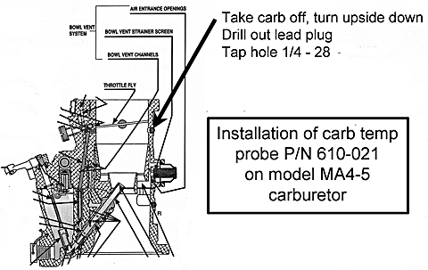
- Question 4, Cessna Carburetor model MA4-5
- Question 5, TIT probe location.
- Question 6, How to adjust brightness.
- Question 7, Check brightness.
- Question 8, Do not bend probes.
- Question 9, Check ground strap.
- Question 10, Check D-Sub Connector.
- Question 11, Check Snap-On Ferrite.
- Question 12, Having a clean ground.
|
a) All warranties begin from Date of
Purchase from Insight
Instrument. |
|
b) Two Year Warranty - TAS 1000, Strike Finder and TF 500. |
|
c) One
Year on G1, Two Year on G2, Three Year on G3 |
|
d) One Year Warranty or 1000 Hours
(whichever comes first) -
Probes/Harnesses/Sensors. |
|
e) 90 Days - Refurbished Units or Repaired
Units. |
|
f) Insight Instrument covers outgoing UPS
Expedited, shipping services. |
|
g) Warranty coverage’s are determined by the Insight Technician only.
|
Carb temp probe P/N 610C-021 installation instructions.
Here is the manual for the Model MA4-5 Carburetor - ![]() Click
Here
Click
Here
Here is the location below
Here's a photo of the aircraft turbo exhaust inlet.
Beech F33A (19xx) with IO-550-B Turbo Flite 550 (turbo
normalized).
Installation of the GSeries engine monitor - Need to know TIT probe optimum location.
Answer
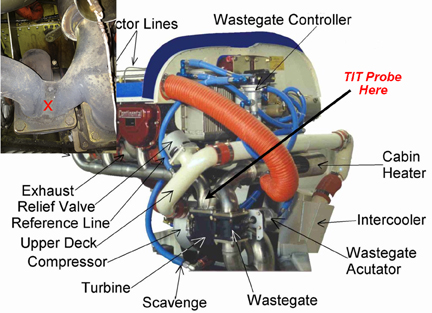
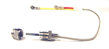
Turbine Inlet Probes (TIT)
TIT Probe 7/16" - 20 P/N 2872 Threaded with boss
K-Type thermocouple Red/Yellow in Yellow
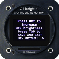
G1 Question:
How do I adjust the brightness on my G1 after the software update.
Answer: You can adjust the minimum brightness on your G1.
Here's how to do this.
1. Power off the G1
2. Remove the SD Card.
3. Press and hold the top button
4. Do NOT release the top button. Turn on the G1 power.
5. Continue to hold the top button for about 4 or 5 seconds
6. Release the top button.
7. Every time you press the bottom button the display will be brighter.
Keep pressing the bottom button until you get the brightness you want.
If you press it many times it will go dim. When you get the brightness you want press the top button to save.
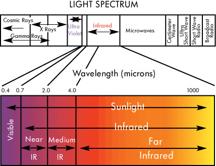
NOTE: To check brightness, use incandescent light source to shine on GSeries instrument face.
LED and fluorescent have narrow wavelength - See charts
The GEM's wiring harnesses should be positioned away
from sources of high energy,
such as ignition harnesses, magnetos, P-leads,
alternator wiring and high frequency radio wiring and
antennas.
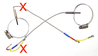
WARNING about installing probes
The minimum radius of bends in wire groups or bundles must not be less than 10 times the outside diameter of the largest wire or cable, except that at the terminal strips where wires break out at terminations or re-verse direction in a bundle. Where the wire is suitably supported, the radius may be 3 times the diameter of the wire or cable. Where it is not practical to install wiring or cables within the radius requirements, the bend should be en-closed in insulating tubing. The radius for thermocouple wire is 20 times the diameter.
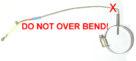
Over bending voids warranty.
The first thing to troubleshoot is do I have a good ground?
How is my ground strap?
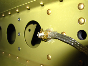
Example of good ground strap
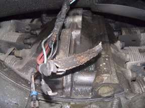
Example of a bad ground strap
If your ground strap is similar to the top picture enjoy your new G Series Engine Monitor.
If your ground strap is similar to the bottom picture you will be talking to Insight tech support.
If you are having erratic fuel flow or any other function other than EGT, CHT or TIT’s please take time to inspect the wiring in the D sub connector on back of G Series monitor.
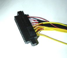
Example of good job
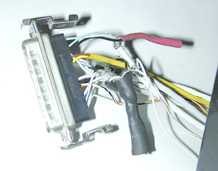
Come on, smarten up!!!
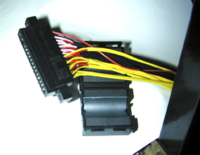
If upgrading from a previous GEM be sure to install the supplied “snap-on” ferrite suppressor over the unshielded wires.
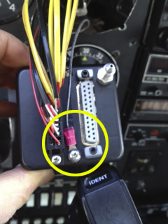
Do NOT ground the G Series monitor or any other instrument to a painted panel – Run a separate ground wire to a CLEAN airframe ground.
![]()