Strike Finder Answers
Ultra Bright Display STRIKE FINDER®
200, 100, 50 and 25nm Weather Avoidance
Installation Skin Map
The STRIKE FINDER® unit can be used to skin map the aircraft.
Here's how:
- Before permanently installing the cable, run it along the outside of the aircraft.
- Connect the sensor and display unit and turn the unit on.
- The display unit should be mounted already in the panel.
- Boot the STRIKE FINDER into dealer mode by holding all four buttons in until the first sunburst occurs.
- After booting a trigger counter will be in the bottom left hand corner.
- Turn ALL aircraft systems on.
- With a helper holding the sensor flat on the aircraft skin, move the sensor to various locations on the aircraft while watching the trigger counter.
- Find an area on the aircraft where the least amount of triggering occurs.
- Ideally, the STRIKE FINDER® should only trigger once or twice every 30 seconds.
Diagnostic Skin Map
- Pull all breakers in the aircraft.
- Turn only the STRIKE FINDER® on and boot the unit into dealer mode by holding all four buttons in until the first sunburst is complete.
- The unit will sunburst 4 more times and 2 rings of dots will appear as well as a trigger counter.
- Press clear to remove the dots that are not needed.
- Begin turning on the aircraft systems.
- Wait at least a minute between each system.
- If the unit begins to trigger, you have just found the problem.
- A correct installation is with all systems turned on and no triggering.
Troubleshooting STRIKE FINDER®
To eliminate strobe noise see - ![]() Strobe
Noise
Strobe
Noise
STRIKE FINDER® has
three antennas inside its sensor. Two are loop-type to
receive bearing signal data, and the third is a sense
antenna. The sense antenna is omni-directional, and the
phase of its output signal is compared with that of the
loops to determine if the strike was on one side of the
aircraft or the other. The basic principles are similar
to those used in Fixed-Loop Automatic Direction Finder
(ADF) for bearing detection. Each antenna outputs a
signal which is sent to the display unit, where it is
digitized and processed for plotting. The loop antenna
signals are defined as X and Y, and the sense signal is
defined as R STRIKE FINDER® is
basically detecting a radio signal radiated from a
vertical electrical discharge (lightning strike), which
may be hundreds of miles away. When diagnosing
interference problems, it is helpful to consider the
fact that a strike with a current of thousands of
amperes, hundreds of miles away, may look the same
(electrically) as a small spark of minimal amperes a few
feet from the sensor. This could be produced by
something as simple as bad brushes on an alternator, or
a loose wire. Therefore, the location and condition of
other electrical equipment and wiring, relative to the
sensor, will influence the success of any STRIKE FINDER® installation,
in terms of electrical interference.
Once the power
is turned on, STRIKE FINDER® automatically
carries out a self-diagnostic test every minute. If a
fault is detected, the appropriate error code is
displayed in the lower left corner of the display, and
the test rate is increased to once per second. Also, the
"walking dot" disappears from the display. When a fault
condition is annunciated in this way, the display may
continue to plot strikes, but the data may not be
trusted for safe storm avoidance. These are the error
codes which may appear: XO, Xl, X2,YO, Yl,Y2, Z, S, B.
To assist in diagnosis of fault conditions, the
following interpretation of error codes is provided.
Reference to Interconnect Diagram 2000-019 in the STRIKE
FINDER® installation
manual.
XO, Xl, or X2 - Continuously Displayed
X channel bandwidth, gain, or phase error. Fault may be in display, sensor, or cable. Check sensor cable/connector wiring for conductors XA and XB.
Exchange display and sensor with known good components.
XO - Intermittently Displayed
This code will disappear
and re-appear, randomly, and may also disappear after
the CLEAR button is pressed.
It may be accompanied by
plotting of a cluster of dots, a line of dots, a
scattering of dots, or no dots at all.
Possible loose
connections on cable/connector conductors XA and XB.
In most cases, this error code is the result of
repetitive current noise being inductively-coupled into
the sensors X and Y loops, at a sufficiently high rate
and amplitude to cause interference with the test pulse.
This causes the test to fail intermittently. Since XO is
the first test in the series, it is the one that shows
up first in a noisy environment. Sometimes however, in
normal operation without the presence of interference, a
high level of storm activity may cause a momentary XO
error to appear. This an acceptable condition, requiring
no operator action.
In order to locate and correct an interference problem, select Dealer Mode on the display, and clear the display. Watch the activity number in the lower left corner. This number is a count of the number of times STRIKE FINDER is triggered. The goal of interference investigation is to reduce the rate of triggering (in the absence of real storm activity) to one every 30 seconds, or longer, and to ensure that no dots are being plotted.
If a cluster or line of dots is being plotted, switch off all other electrical equipment in the aircraft, and clear the display. If dots appear again in the same location, rotate the aircraft and again clear the display. If the dots appear at a new location, the interference source is external to the aircraft, and further testing may not be necessary. If the dots appear at the same location, no matter what the aircraft heading, then the source is on the airframe or is being generated by the STRIKE FINDER® system itself.
Connect the display to a
separate battery, and switch off the aircraft master
switch. If dots continue to appear at the same location,
the STRIKE FINDER® is
generating its own dots, and both display and sensor
must be returned for repair.
If the display is not
plotting dots at this point, and the activity number is
now stable, begin switching on various electrical
devices, one at a time, until the activity number begins
to increase. Use this technique to identify interference
sources. All systems should be activated, including trim
motors, strobe lights, DME, transponder, and engines.
The most common sources are alternators, strobe lights,
and trim motors.
To assist in this procedure of identifying interference sources the Insight Audio Tester (P/N 2000-060) may be used.
YO, Yl, or Y2 -Continuously displayed
Y channel bandwidth, gain,
or phase error. Fault may be in display, sensor, or
cable. Check sensor cable / connector wiring for
conductors YA and YB.
Exchange display and sensor
with known good components.
YO - Intermittently displayed
This code will disappear
and re-appear, randomly.
Possible loose connections
on sensor cable/connector conductors YA and YB.
Or
Y
ou lost the rubber O ring that was inside the Strike Finder sensor connector - "See picture"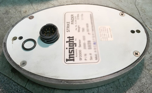
P - Continuously displayed
P channel failure, or sense
antenna fault.
Check sensor cable / connector wiring
for conductor PF.
Exchange display and sensor with
known good components.
P - Intermittently displayed
This code will disappear
and re-appear, randomly. When a real storm cell is being
plotted on the display, a mirror image', or ambiguous
storm cell will be plotted, usually with fewer dots than
the real storm cell. In Dealer Mode, the activity number
will usually be acceptably stable.
Possible loose
connection on sensor cable/connector conductor PF
In
most cases, this error code is the result of repetitive
voltage noise being coupled into the sense antenna at a
sufficiently high rate and amplitude to cause
interference with the test pulse. This causes the P
channel test to fail intermittently.
Use the Insight Audio
Tester (P/N 2000-060) to isolate the interference
source, by switching various electrical equipment on,
one at a time.
The most common voltage noise sources
are DME, transponder, and navcom,
Ensure that all
sensor cable shields are connected to pin 1 0 of the
display's DB25 connector.
Check DME, transponder, and
navcom antenna coax terminations as indicated.
Check
shields, grounds, and power supply filters on relevant
interfering equipment.
Z - Slow Flashing
This error code can result
from loss of +8V or -8V supply, or ground to the sensor.
Also, loss of the test pulse signal to the sensor, or
sensor malfunction will produce this error code.
Check for the presence of +8V and -8V at the sensor 9
pin connector.
Check sensor cable/connector wiring
for conductors +8V, -8V, GND, and TG.
Exchange
display and sensor with known good components.
S - Continuous
Separation failure in test
pulse hardware.
Return display to Insight for repair.
B - Continuous
Non-volatile memory
failure.
Return display to Insight for repair.
Other Symptoms
Mirror Imaging
Symptom: Display
plots a real storm cell at the proper location, as well
as a mirror image', or ambiguous cell located
180-degrees away. Usually the mirror image cell has
fewer dots. This condition may be accompanied by an
intermittent P error message.
For troubleshooting,
see 'P-Intermittently Displayed', above.
STRIKE FINDER® Install Note
- It is important to skin map the aircraft before installation of the Strike Finder®. The Strike Finder® unit can be used to skin map the aircraft. Here's how:
- Before permanently installing the cable, run it along the outside of the aircraft. Connect the sensor and display unit and turn the unit on. The display unit should be mounted already in the panel. Boot the Strike Finder��into dealer mode by holding all four buttons in until the first sunburst occurs. After booting a trigger counter will be in the bottom left hand corner. Turn ALL aircraft systems on. With a helper holding the sensor flat on the aircraft skin, move the sensor to various locations on the aircraft while watching the trigger counter. Find an area on the aircraft where the least amount of triggering occurs. Ideally, the Strike Finder® should only trigger 1 or 2 times every 30 seconds.
Composite Plane
- The installation of the Strike Finder® in a composite plane requires special installation. The most important point being the ground plane. The doubler plate in a normal installation is grounded to airframe ground through the ground strap. In a composite plane, the doubler plate should be approximately 4 times larger and also needs to be grounded to the airframe through a ground strap. You will probably have to run the ground strap to the front of the aircraft for the airframe ground.
- In a composite
aircraft like the Glasair, the doubler plate used
for mounting the Strike Finder® should
be approx. 4 times larger than what is used in a
metal aircraft. This doubler plate is made by the
installer. It needs to be connected to the airframe
ground by use of a static strap. Also, ensure that
the Strike Finder® sensor
is mounted in an electrically isolated area on the
aircraft. No equipment such as, trim motors, beacons
or strobes, DME/transponder, etc. are notorious
noise sources and should be properly isolated from
the Strikefinder®.
.
Aircraft Noise.
Try this testing procedure to help indicate where the noise may be occurring.
Testing should be done in a metal aircraft hangar with the door closed. Ensure that the area is electrically quiet.
1 - Pull all breakers in the aircraft. Turn only the Strike Finder® on and boot the unit into dealer mode by holding all four buttons in until the first sunburst is complete. The unit will sunburst 4 more times and 2 rings of dots will appear as well as a trigger counter. Press clear to remove the dots which are not needed. If the unit is triggering greater than 1 per 30 seconds and/or dots are being plotted and/or an error code appears, go to line 2. If not, go to line 5.
2 - Press clear to clear the display and ensure that ALL aircraft systems are off. If the unit is triggering greater than 1 per 30 seconds and/or dots are being plotted go to line 3. If not, go to line 5. If an error code appears continuously, go to line 9.
3 - Rotate the aircraft 90 degrees. If the unit is triggering and/or plotting dots at the same location relative to the aircraft heading, go to line 4. If the unit is triggering and/or plotting dots at a different location relative to aircraft heading, go to line 7.
4 - Connect the Strike Finder® to a separate battery external of the aircraft. Switch off the master avionics switch if not already. If the unit is triggering and/or plotting dots at the same location, go to line 8. If the unit is not triggering and plotting dots, go to line 5.
5 - Begin turning on the aircraft systems. Wait at least a minute between each system. If the unit begins to trigger, go to line 6. A correct installation is with all systems turned on and no triggering. No further testing is required. If the unit still gives an intermittent error code after all testing is complete, go to line 9.
6 - Inspect the interfering source for correct operation. Move the sensor or offending system to isolate the noise. Go to line 5 until all systems have been turned on.
7 - External noise is causing the triggering and/or plotting. Choose a quieter location and ensure no active storms are within 200nm. Go to line 1.
8 - The Strike Finder® may be generating its own dots and/or causing the triggering itself. Contact Insight for more information.
9 - The Strike Finder® may need repairs. Contact Insight for more information.
This test will help to ensure a correct installation. The goal of the test is to reduce interference and reduce the triggering of the Strike Finder® to less than 1 per 30 seconds. The most common noise sources are strobes and beacons, DME/transponder, trim motors and servos.
Plotting of dots from 10:00 to 4:00 with an intermittent X0
- The plotting of dots from 10:00 to 4:00 with an intermittent X0 is a clear indication of noise in the aircraft. Here is a procedure I would like you to do to help isolate where the noise is occurring. Please do this test in a metal hangar with the doors closed and with as little electrical activity in the hangar as possible.
- Ensure ALL aircraft
systems are off. Turn only the Strikefinder® on.
- Boot the
Strikefinder® into
dealer mode by pressing and holding all 4 buttons
until the first sunburst occurs and release. The
Strikefinder® will
sunburst 4 more times and a trigger counter will
appear in the bottom left hand corner. The rings of
dots are not needed. Remove these by pressing clear.
- Note that the
Strikefinder® should
not be counting or plotting dots. If it is counting,
please contact Insight for more information.
- Begin turning on your aircraft systems slowly. Watch the trigger counter for an increase is counting. The goal is 1 or 2 triggers every 30 seconds for an ideal installation. When the counting increases rapidly, a noise source has been identified. Either move the offending source or relocate the Strikefinder® sensor to a quieter area on the aircraft. Contact your avionics shop for help in this regard.
If you have any further questions, please don't hesitate to contact us. Our number is 905-871-0733.
TECH SUPPORT #2
Troubleshooting STRIKE FINDER®
QUESTIONS AND ANSWERS
- How long does a dot stay on the display?
- The dots will stay on the display as long as strikes occur.
- How often or when should I press the clear display button?
- Clear the STRIKE FINDER® display to evaluate storm intensity. See Display Interpretation section for details.
- If I have selected the 25 nm range view, will STRIKE FINDER® be still gathering data at 200 nm?
- Yes, STRIKE FINDER® is always gathering and analyzing data out to 200 nm.
- Does size or brightness of dots indicate strength of lightning strikes?
- No. The severity of the lightning strikes are assessed in several ways. See Assessing Storm Severity section for details.
- What is the cause of an X0 error appearing intermittently?
- The X0 error message indicates failure of STRIKE FINDER® self-test. The failure may be temporary or permanent. See the Trouble Shooting section for details.
- Is the STRIKE FINDER® a Heading-up or a North-up display?
- STRIKE FINDER® is a Heading-up display.
- Will Strike Finder slave to an autopilot?
- No, it may be slaved to a 400 Hz synchro-resolver interface, or a Bendix/King KCS-55 stepper interface.
- Can STRIKE FINDER® be interfaced to a radar display?
- No, all radar display instruments have proprietary interfaces.
- I see "flickering" dots, what does this mean?
- Flickering may be caused by a faulty plasma display, or a faulty photo cell. Call Insight technical support.
- Can STRIKE FINDER® detect anything other than thunderstorms?
- No, STRIKE FINDER® will only detect lightning strikes.
Electrostatic Charging In Flight
by: Jay D. Cline, Dayton-Granger, Inc.
It is widely known that electrostatic charging of aircraft in flight generates radio frequency noise which disrupts navigation and communications. Such charging results from several sources. For example: Flight through precipitation, electric cross fields and engine produced ionization. RF noise is also generated by streamer currents on the plastic frontal area of an aircraft during precipitation encounters and corona discharge between airframe members.
This can affect almost all aircraft, from General Aviation through airline transport and military supersonic. At ground speeds of two to ten nautical miles per minute, loss of navigation or communication due to streaming, corona or arcing noise can be serious, especially while maneuvering near airports in instrument conditions.
Static Discharge Story
In the early days of aviation, flying was done primarily during daylight by visual reference such as highways, railroad tracks and rivers. Communication was done by signal lights and wing waggling.
As the reliability of aircraft improved, flying under all conditions became practical, creating demands for improved communications and navigation systems. However, during the early use of these systems, pilots quickly became aware of a form of severe radio interference which hampered the performance of the existing navigation and communication systems.
Experience showed a correlation between RF noise and flight through rain, snow and clouds. Hence, pilots became very concerned because the conditions which caused the most "precipitation static" (P-Stat) occurred when navigation and communication needs were the greatest.
Aircraft Charging
These effects occur as an airplane flies through freezing rain, ice crystals, dusts, sand and snow. Contact with these particles leaves a positive or negative charge on the air frame. As the aircraft charge builds a potential is reached where the charge leaks off the aircraft and antennas, generating broad band radio frequency noise. This interferes with ADF, HF, as well as VHF and VOR receivers.
Cross-field currents are generated on aircraft flying in clear air beneath a charged cloud layer. The magnitude is a function of the potential of the cloud with reference to ground and the speed of the aircraft.
Streamering
This noise source is generated over dielectric surfaces such as radome's, fiberglass winglets and other fiberglass panels positioned on frontal impact areas of the aircraft. As particles strike, they deposit an electron on the dielectric surface. As more particles impact this isolated pool, the voltage increases until it reaches the flash over point. When the pool of charge flashes over the surface of the dielectric material, it generates broad band radio frequency noise.
This phenomenon is also observed over metal surfaces painted with a high electric strength paint, or paint buffed to a high polish. In this case, charges accumulating on the paint generate streamers to a rivet head or screw fastener. Streamering can be solved by coating the non-conductive surface with high resistance paint. Such paint quietly bleeds the charged particles to the aircraft fuselage.
Corona Noise
This occurs when the aircraft accumulates sufficient charge due to aircraft charging and/or cross fields to ionize air around wing tips, vertical or horizontal stabilizers and the other protrusions. Over 5,000,000 volts have been measured on General Aviation aircraft in flight. As current bleeds off trailing edges, it generates radio frequencies that sound like loud hissing in aircraft receivers. The charging also causes antennas to go into corona (bleeding off charge). When this happens the noise appears like a strong signal to the receiver. In some cases the automatic gain control circuit, sensing noise as a strong signal, desensitizes the receiver to the point where the receiver may go perfectly quiet. The Pilot assumes no one is calling, but in reality corona current has, for all practical purposes, shut down the receiver. When aircraft voltage lessens and antenna corona current stops, receiver AGC returns to normal and communications can continue. The pilot is seldom aware of what happened. When communications are reestablished, ATC may assume the pilot was not paying attention to his radio.
Solutions to corona noise include antennas that are insulated from space and static discharges positioned where the aircraft is most likely to go into corona; wing tips, vertical and horizontal stabilizers are examples. Static discharges bleed of charge quietly. They lower aircraft voltage below a level where antennas go into corona.
Arcing Noise
This interference is generated by an isolated piece of metal situated on an aircraft where, as the aircraft charges, it reaches a potential at which a spark jumps the gap from aircraft structure to isolated metal. The spark can produce broad band noise extending through 1,000 MHz. The cure is to locate the isolated metal and band it to the aircraft structure grounding strap. To locate this problem, the aircraft can be probed with an Electrostatic Test Set while monitoring aircraft receivers for arcing noise. When the noise area is identified, physical identification can isolate the piece of metal. These and other solutions can greatly lessen the effect of environmentally induced noise while in flight.
During WWII it was necessary to have navigation and communication systems that were reliable in all weather conditions. To address the interference problem the Naval Air Development Center (NADC) sponsored a program to develop methods to reduce noise created by P-Stat. As a result of this program, Dayton-Granger invented and patented the first static dischargers.
Continued research and development in the 1950's led a static discharger which adopted a new concept that was far superior in noise suppression than anything else. This patented device, designed the Granger Associated (later to be a part of Dayton-Granger) was the Nullified Discharger which is still the industry standard today.
FACTORY SERVICE PROCEDURES
Like most modern and sophisticated digital products, the STRIKE FINDER® is exceptionally reliable. After configuration during installation, STRIKE FINDER® requires no adjustment or routine maintenance
Most problems are traceable to wiring, connectors, and interference. The instrument is the least likely cause of trouble.
When the diagnostic procedures described above indicate that the display and/or sensor require service, they must be returned to the factory. Please call INSIGHT AVIONICS before shipping. Ensure that a detailed description of the problem is included with the returned instrument. It is helpful to our technicians if you tape a business card or note to the STRIKE FINDER® so that you may be contacted to discuss the problem and solution. Once repaired, the unit will be returned to you 2nd day, with shipping prepaid if it is still under warranty. Note: Customer pays the difference for next day shipping. If the unit is no longer under warranty, customer pays full shipping charges.
As a STRIKE FINDER® owner, if you have any concern about the operation of your instrument, discuss it first with your dealer. Insight Avionics Customer Service can be reached at any of the following numbers:
- Phone: (905) 871-0733
- FAX: (905) 871-5460
We welcome the opportunity to help you, answer questions, and ensure that you have problem-free equipment that you can use with confidence. Insight provides customer support at no cost, providing you own the equipment. The Customer Service Department is available to you Monday through-Friday, between 9-am and 5-pm EST. Be ready to provide the following:
Type of Aircraft:
Make/Model/Year:
STRIKE FINDER® Display Serial Number:
Sensor Serial Number:
External RBS Serial Number:
![]()