STRIKE FINDER
 Ultra Bright Display
STRIKE FINDER®
Ultra Bright Display
STRIKE FINDER®
200, 100, 50 and 25nm Weather Avoidance
Innovative technology only at Insight now brings you a display that is brighter than direct sunlight.
New Ultra Bright LED Display.
Or...
Upgrade your existing plasma display to our
New
Ultra Bright LED Display.
Note: The Plasma Display has been discontinued.
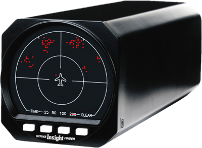
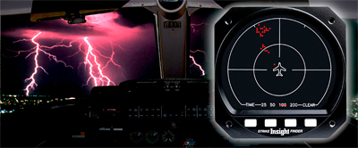
The STRIKE FINDER® Digital Weather Avoidance System detects and analyzes the electrical activity emanating from thunderstorms within a 200 nautical mile (nm) radius of the aircraft. A unique graphic display plots an accurate, reliable and easily-interpreted picture of electrical activity, that you can use to circumnavigate the hazards associated with thunderstorms.
The STRIKE FINDER® System analyzes the individual strike signal properties to determine the bearing, range and severity of the activity. Strike data is plotted on the display as single orange dots by range and azimuth, in relation to the aircraft symbol ("heads up"). As the number of lightning strikes increase, so does the number of plotted strike dots. Cells start to form indicating increased lightning activity.
Bearing and Range
Storm distance and bearing can be determined by using the Outer Range Ring and the Half Range Ring, in conjunction with the 30-degree Azimuth (1:00 and 11:00) markers.
The Outer Range Ring is the outer boundary distance from your aircraft that strike dots are plotted in the selected range. The Half Range Ring is exactly half that distance from your aircraft. (Ex: 200 nm range selection gives a Half Range Ring distance of 100 nm).
STRIKE FINDER System Components
STRIKE FINDER® has two components: These two components are connected with a shielded cable.
Display - The Display mounts in the aircraft instrument panel. The STRIKE FINDER® can be slaved directly to an HSI or compass system with a standard stepper or synchro-output. The display is available with a New Ultra Bright LED Display with a single microprocessor-based circuit board that employs Digital Signal Processing, to ensure that the truest possible storm image is displayed. The microprocessor constantly monitors the performance of the entire system, from the Sensor to the Display for proper function.
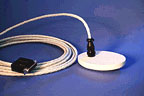
Sensor - The maintenance-free Sensor is weather-sealed and mounts on the outside of the aircraft fuselage. STRIKE FINDER®, unlike any other system, uses Broad-band Digital Sampling. A greater bandwidth delivers vastly more information for improved signal fidelity and inherently superior noise rejection. This translates into a clearer definition of weather activity, without false or misleading indications.
See how the LED STRIKEFINDER display is made
A must-read when thinking about lightning detection in your aircraft.
When Glass Breaks - http://www.rapp.org/archives/2011/01/when-glass-breaks/
Strike Finder Display Options and Differences
There are three types of Display bezels and three possible mounting configurations.
- Display P/N 2000-021-009 mounts in a 3.125 inch round hole.
- Display P/N 2000-021-026 has an integral mounting flange and mounts in a ATI3 octagonal hole from front to rear.
- Display P/N 2000-021-027 has no mounting holes and fits an ATI3 octagonal hole and is supported by a clamp tray or clamp fixture.
The first configuration is ideal for use in an existing 3.125 inch round hole, or when a panel hole must be cut. In most cases, a round hole is easier to create than and ATI3 style, unless a punch kit is used to create a uniform mounting hole.
The second configuration is intended for use in an existing ATI3 instrument hole when front or rear flange mounting is desired.
The third configuration is best for the replacement of existing clamp-mounted instruments.
Note that a special Sensor, P/N 2000-024, is available for installation on jet aircraft.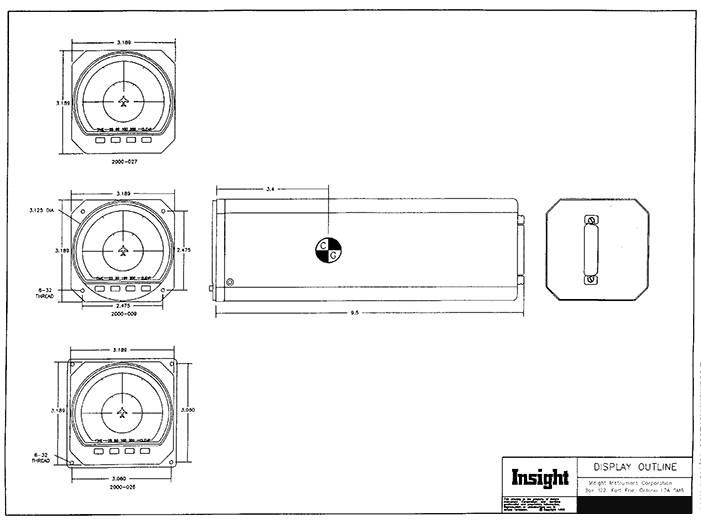
REVOLUTIONARY BREAKTHROUGH FOR STRIKE FINDER!
INSIGHT'S STABILIZATION MODULE ELIMINATES THE NEED FOR SLAVED COMPASS SYSTEM
Traditionally, weather mapping
systems require connection to the aircraft's slaved compass
system to maintain correct data orientation through heading
changes. Recognizing that not all aircraft are equipped with a
slaved compass system, Insight developed the Stabilization
Module.
The Stabilization Module provides data to the STRIKE
FINDER®, enabling displayed lightning strike information to
rotate relative to heading changes. Operation of the
Stabilization Module is automatic; no field configuration or
calibration are required.
THE REVOLUTIONARY STABILIZATION MODULE;
- Internal installation only.
- Eliminates the need for a slaved compass system.
- Is a totally self-contained sensor and data processor.
- Contains no rotating gyro.
- Gone forever are those periodic overhauls that are necessary with common rotating gyro systems.
LATEST TECHNOLOGY
The Stabilization Module contains all solid state components; there are no moving parts. New software algorithms process data from the enclosed sensors to determine heading change. Insight has developed this state-of-the-art stabilization system, by integrating both the motion sensor and the data processor into one miniature module. Benefits include reduction in cost, complexity and weight of a conventional system.
FACTORY OPTION ONLY
As a factory installed option, the Stabilization Module is now only installed
within the STRIKE FINDER® housing, deriving its power from and providing its
signals directly to the STRIKE FINDER® processor. Insight recommends the STRIKE
FINDER® System with the Factory Option, even for
slave-compass equipped aircraft.
This installation is simpler, faster and offers enhanced reliability by eliminating dependence on the maintenance-intensive rotating gyro.
FACTORY CALIBRATED
Each Stabilization Module is individually factory calibrated and tested to insure proper operation under all conditions.
Call now for a price and a dealer near you.
![]()